Goal
Design a network attached mmWave radar switch for use with Home Assistant. The switch will be used to detect human presence and turn on one or more lights.
The following steps will be required to complete this project:
- Test the Radar module.
- Implement the UART communication protocol to enable configuration of the module.
- Write FW for the ESP32 to communicate with the radar module and over the local network to home assistant via a MQTT or a similar protocol.
- Design a Radome and mechanical enclosure for the Radar module and MCU, including provision for wall mounting.
- Fabricate and assemble the enclosure and device.
- Implement the completed network device in Home Assistant.
The Radar
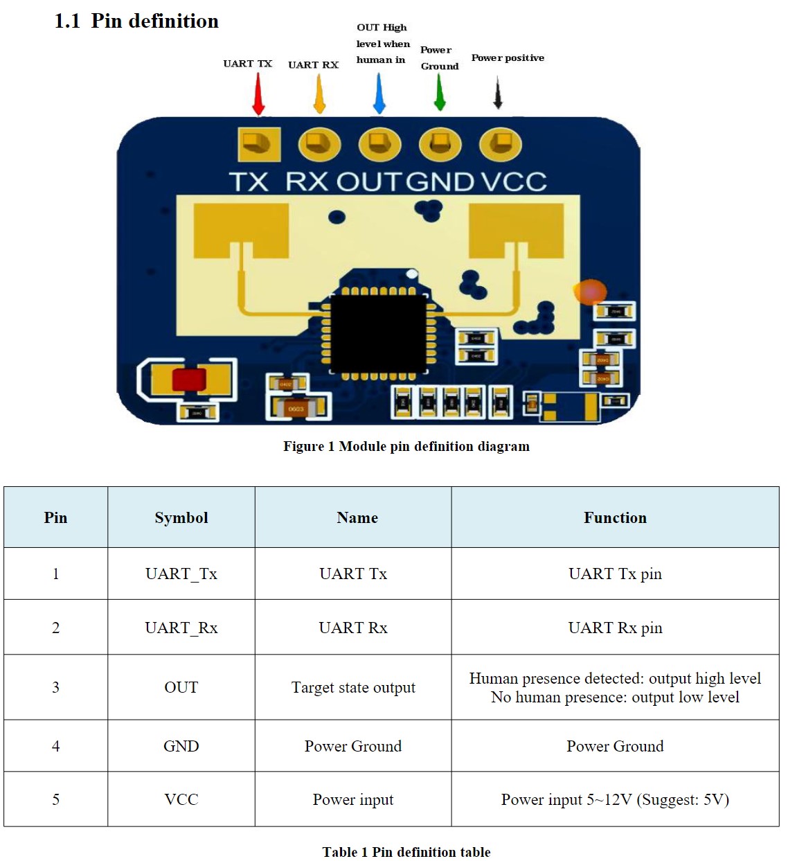
The mmWave radar sensor module used will be an HLK-LD2401C. This module has a digital output which goes high when a person is detected. The module has bluetooth capability to enable configuration from a smartphone app. A UART port also provides access to configure the device settings. Bluetooth configuration will not be used. (The app and instructions are in Chinese.) UART will be used to disable the bluetooth for security and power saving reasons. The module will be connected to a network enabled MCU to allow connection to home assistant.
Choosing an MCU
As the sensor will require network access to interface with Home Assistant an MCU with WiFi capability will be selected. For wide ranging support and ease of programming either an ESP32 or ESP8266 will be used, or alternatively a RP2040-W or analogous device could be used.
In this case I used an ESP32, specifically an ESP32-DEVKIT-V1 with an ESP32-WROOM-32 module. This was chosen for its low cost and high availability (i.e. I already had one in my draw).
Programming the ESP32
The ESP32 will be programmed using Platform IO. Platform IO is a Visual Studio Code extension that allows programming of many varieties microcontroller, along with the benefits of Visual Studio Code’s GitHub integration and large collection of extensions.
UART Communication Protocol
The UART protocol for the mmWave radar is defined in the document: https://naylampmechatronics.com/img/cms/001080/Protocolo_comunicacion_serial_LD2410C.pdf
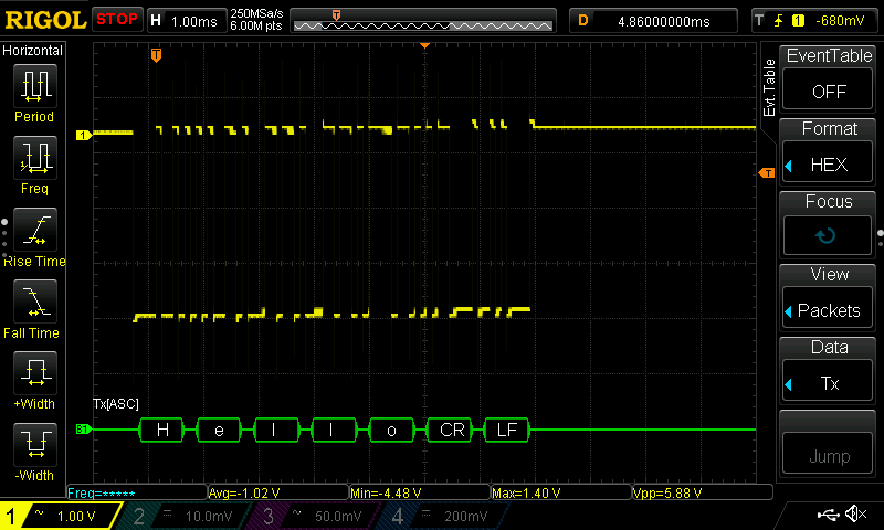
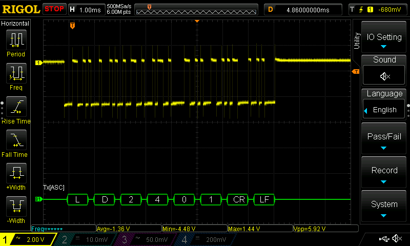
Before implementing a library to handle the communication with the LD2401C, I will test the Serial port of the ESP32 module using the Rigol DS1054Z Oscilloscope. This will verify that the device programming from Platform IO is working, and the oscilloscopes decode function can accurately provide a display of the information sent, and later received, to aid with the implementation of the UART protocol for the LD2401C.
In order to test the UART transmit output and verify the scopes decode function the following simple code was written using UART 2 of the ESP32. The code establishes UART on UART 2, sets the baud-rate, parity and stop-bits, along with the GPIO to be used for RX and TX and transmits ASCII “Hello” once per second.
#define RX 16
#define TX 17
#define UART_BAUD 9600

HardwareSerial HLK_UART(2);

void setup() {
  HLK_UART.begin(UART_BAUD, SERIAL_8N1, RX, TX);
}

void loop() {
  HLK_UART.println("Hello");
  delay(1000);
}
The oscilloscope is set to RS232 decode under the “Math” menu with settings matching those in set in the FW, enabling “Hello” to be read:
Using the Event Table allows for display of more bytes:
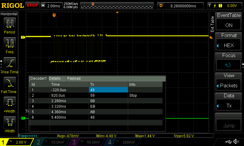
This confirms that the UART transmits successfully and the decode function is working. Implementation of the LD2401C UART protocol will be done after testing the module is functional.
Testing the LD2401C mmWave Radar Module
In order to test the LD2401C mmWave radar is functional, the digital output was connected to the ESP32 GPIO13 pin. The LD2401C was powered from 5V supplied by the USB connection for the ESP32, accessible via the Vin pin on the dev kit.
Some simple code was written to turn on the Dev Kit’s on board LED when GPIO5 reads a high output from the LD2401. In this way the functionality in the basic factory settings could be tested to confirm the module is working prior to proceeding further.
#define LD2401_OUTPUT 13

#define LED_ON digitalWrite(LED_BUILTIN, HIGH)
#define LED_OFF digitalWrite(LED_BUILTIN, LOW)

void setup() {
  pinMode(LED_BUILTIN, OUTPUT);
  pinMode(LD2401_OUTPUT, INPUT);
}

void loop() {
  if(digitalRead(LD2401_OUTPUT) == HIGH)
    LED_ON;
  else
    LED_OFF;
}
After uploading the code the onboard LED lit up. Walking >6ft away from the module and waiting for the default “no man duration” to occur, the LED switched off.
INSERT IMAGE OF CONNECTION HERE.
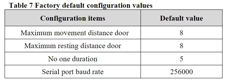
The “no man duration” is the duration between when the radar no longer detects a human presence and the OUT pin goes low again. Per the LD2401C Serial Communication Protocol document the default settings are:
Making a library in Platform IO
For libraries to be compiled and included in the build using Platform IO, the source code of each library should be placed in its own separate directory
(“lib/your_library_name/[here are source files]”).
In this case the following structure was used:
|–lib
|–|–HLK-LD2401C-UART
|–|–|–HlkUartLd2401.h
|–|–|–HlkUartLd2401.cpp
A much simplified version of a library was created in order to confirm the structure was correct, it could be successfully built, and the serial communication was working. The library takes a HardwareSerial instance and transmits “LD2401” over the ESP32 UART 2 port.
The .h file was as follows:
#ifndef HlkUartLd2401_H
#define HlkUartLd2401_H

#include "Arduino.h"

#include <stdint.h>
#include <stdlib.h>

#define DEFAULT_BAUD  9600

class HlkUartLd2401 {
    public:
        HlkUartLd2401();

        void begin(HardwareSerial& serial);

        int16_t transmit();

    private:
    HardwareSerial* _serial = nullptr;
};

#endif
The .cpp file was as follows:
#include "Arduino.h"
#include "HlkUartLd2401.h"

HlkUartLd2401::HlkUartLd2401() {
}

void HlkUartLd2401::begin(HardwareSerial& serial) {
    _serial = &serial;
    _serial -> begin(DEFAULT_BAUD);
}

int16_t HlkUartLd2401::transmit() {
    _serial -> println("LD2401");
    return NO_ERROR;
}
The test main.cpp used to check the serial decoding was modified to use the new library:
#include "HlkUartLd2401.h"

#define RXD2 16
#define TXD2 17

HardwareSerial HLK_UART(2);
HlkUartLd2401 LD2401;

void setup() {
  LD2401.begin(HLK_UART);
}

void loop() {
  LD2401.transmit();
  delay(1000);
}
The ESP32 was programmed and the TX2 pin was probed to verify the expected output:
LD2401C UART Communication
The UART Rx and Tx are broken out on pins 1 and 2 of the module:
The UART protocol for the mmWave radar is defined in the document: https://naylampmechatronics.com/img/cms/001080/Protocolo_comunicacion_serial_LD2410C.pdf
The LD2401C module IO output level is 3.3V.
By default the baud rate is set at 256000, with 1 stop bit and no parity bit.
Data is sent little-endian, and documented in hexadecimal.
The UART serial TTL port can be used to configure the device, enabling modification of values such as:
- The farthest detection distance
- Sensitivity
- “no-one duration”
- Bluetooth settings
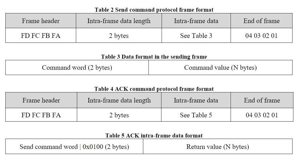
The command and response data frames consist of the following four parts:
- A Frame header (FD FC FB FA)
- Intra-frame data length
- Intra-frame data
- End of Frame (04 03 02 01)
The data included in each frame consists of two parts:
- the Command Word (2 bytes)
- the Command Value (N bytes, specified in the Intra-frame data length part)
The frame Header and End are consistent across all commands in order to differentiate the beginning and end of a frame.
The received ACK data follows the same format except the Command Word undergoes a bitwise OR with the value 0x0100.
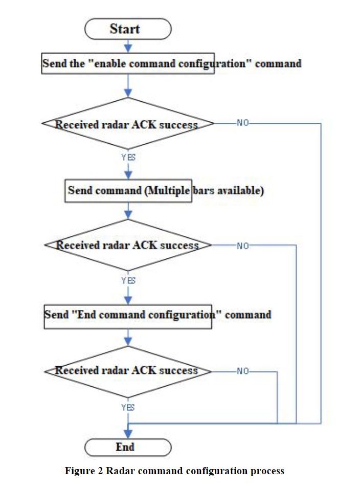
In order to change the radar settings the device must first be put in to configuration mode using the enable configuration command:
Command word: 0x00FF
Command value: 0x0001
Once the settings have been changed the device must be returned to working mode by issuing the end configuration command:
Command word: 0x00FE
Command value: None
The following flow chart demonstrates the steps that must be taken to properly configure the radar via UART:
The various command words, values, and responses for individual settings can be viewed in the document linked above.