This is the first post in a series documenting the development of a WiFi enabled LED array based display. The display will be used to show the current local weather forecast, provide indicators for Fire and Wind warnings, as well as likelihood of precipitation.
What is an LED Array?
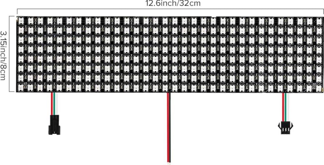
The LED array I will be using is a commonly available array of WS2812B programmable RGB LEDs on a flexible PCB substrate. The array in question is 8x32 LEDs (Amazon PN ASIN:B01DC0IPVU). Other sizes are available.
Here is the link used to purchase it: https://www.amazon.com/BTF-LIGHTING-0-24ft0-96ft-Flexible-Individually-addressable/dp/B01DC0IPVU

Why use an LED Array?
Why use an LED array rather than an LCD, OLED, smartphone, or similar display which can show far more detailed text and numbers?
While cost could be a major factor, the primary reason for using an LED array is for the ease and potential speed of information transfer. For example an LED array by the front door of your home with an indicator light for chance of rain would be an almost instant reminder to grab your umbrella. The colour and intensity of the LEDs might be a quick visual indicator that today will be hot and you don’t need your jacket. An indicator light for a High Wind alert might remind you to secure some items in your garden.
Some secondary reasons are:
- Glowing LEDs are cool.
- It’s a good excuse to learn a range of skills including embedded programming, web APIs, 3D CAD and printing etc.
- I have an LED array already…
Development process
- Concept generation.
- Define requirements: What do we want the display to do?
- Define initial specifications: What do we need to do to meet the functions set out in the requirements?
- Prototype: Make an initial minimum viable prototype to use for POC testing and feed back into the specifications.
- Design: Take learnings from prototype stage and do the HW/FW development to create a full device.
- Test: Test the device to identify issues and ensure that it meets the specifications.
- Iterate: Repeat steps 5 and 6 until satisfied. (This is a one-off device so no need for DFM/scalability etc. beyond that needed to produce a functional and cosmetically acceptable device.)
Getting started: The LED Array
How does the LED array work? What can it do? How is it it controlled?
The LED array contains 256 5x5mm WS2812B LEDs in an array of 8 rows and 32 columns.
The LEDs are evenly spaced at 10mm intervals and the full array, including the substrate, measures 320mm x 80mm.
There are three input wires, two for a 5VDC connection and one for Data input. A further three wires provide outputs for daisy-chaining additional arrays.
The WS2812B LEDs are individually addressable and each contain an integrated control circuit. This control circuit can control the brightness and R,G,B colour of the light. They are very common due to their low cost, ease of use, and community and library support.
If all you are interested in is a WiFi controlled LED array with built in lighting effects, timers, smartphone app and no specific software control over the lights, look up WLED.
What does this mean for the display?
Individual control of each LED brightness and colour enables ability to create indicator lights, bar chart like features, animations etc. that can be used to create a display.
Display features:
Bar charts
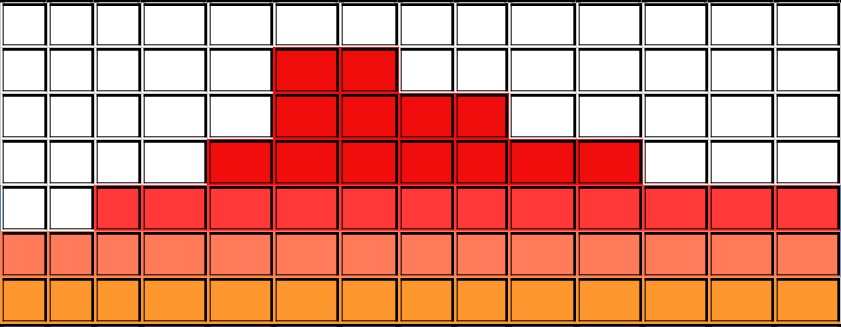
Individual columns of LEDs can be used to create a display analogous to a bar chart:

Varying the colour and brightness of the bars can add further information to each bar.
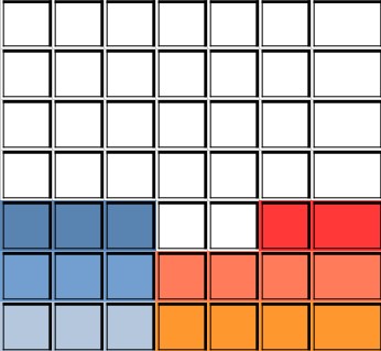
For example the sunset/sunrise day/night transitions could be indicated by the base colour of the bars like so:

The height of the bar charts could indicate a value, such as temperature. Above or below a certain threshold temperature the colour could change in hue or brightness to indicate freezing for example.
Other features
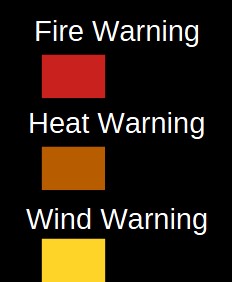
Individual LEDs can be used as indicator lights. Hue, brightness and flashing could add further information helping to condense what may be a vertical column of LEDs to an individual light.
Eg. for Warnings:

Individual Brightness showing magnitude of precipitation probability:

Defining Requirements
As this is a one-off device and the possibilities are constrained by the requirement of using the already purchased LED array the requirements can be kept simple.
- The device shall display:
- Hourly weather for the current 24 hour period (midnight->midnight).
- Hourly precipitation probability for the same period.
- Current Humidity.
- Current Air Quality.
- Regional Weather Alerts such as Red Flag Warnings, High Wind warnings etc.
- The finished device needs to be connected to WiFi to access the data to drive the display.
- The device shall be powered over USB from a standard charging block, if the current draw allows for it.
- The device shall have a diffuser for the LEDs.
- The diffuser may contain text or images to label the indicators.
- The device enclosure should be 3D-printable.
- Any screws used shall be common Metric screws, preferably M3.
- Any APIs used to collect the weather data should be free and open and not require and account.
An initial display concept.
With the basic requirements and an idea of some of the ways in which the LED array might be used to display information an initial layout concept for the display can be made:

The display is broken up into sections:
-
Hourly temperature over 24 columns, one for each hour of the day:

-
Hourly precipitation over 24 individual LEDs:

-
Weather Alert indicators on individual LEDs:

-
Individual columns for current relative humidity, wind speed & air quality index (AQI):

Part 2: Working with the WS2812B LED Array .