Part 2 of Designing a WiFi enabled LED Array Weather Display.
Choosing an MCU
As the display will require internet access to collect the weather data an MCU with WiFi capability must be selected. For wide ranging support and ease of programming either an ESP32 or ESP8266 will be used, or alternatively a RP2040-W or analogous device could be used.
Sending data to the LEDs
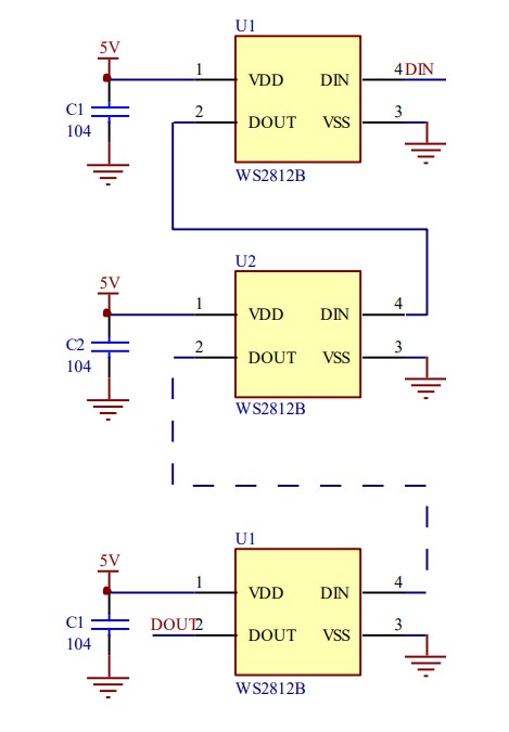
The WS2812B LEDs ar individually addressable. They use a custom single wire communication protocol and this one wire can be used to control each of the LEDs on the array. The Data In wire is connected to the Data In pin of the first LED of the array, the data out pin of this LED is connected to the Data In pin of the next LED and so on for each subsequent LED in the array.

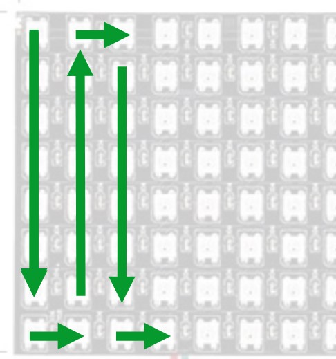
The LEDs are set up in a serpentine pattern beginning at the top left of the array and then alternately working down and back up each subsequent column like so:

Communication Protocol
Due to the single wire protocol the entire array can be controlled from an individual GPIO pin on the host MCU. The data received at the first LED is buffered before being sent on to the next LED to prevent accumulated distortion in the signal for up to 5 meters between LEDs. This will likely help later when attempting to drive the array from a 3.3V GPIO.
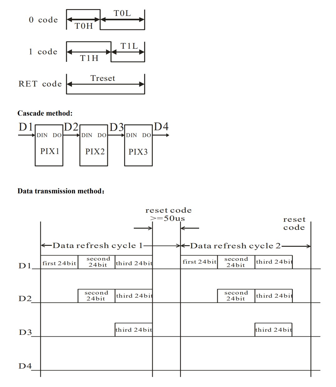
The data is transmitted at a speed of 800Kbps and the value of individual bits are determined by the width of each logic high pulse. This enables a clock and data on the same line. For each clock pulse the line is driven high, with a 0.4us pulse interpreted as a logic low (0) and a 0.8us pulse as a logic high (1). Low voltage for above 50us results in a reset code.
The data is sent in 24bit packets for each LED. Each packet of 24bits is read in a cascading manner down the strip until no more packets are left, with the first 24bit value controlling the first LED, the second 24 bit value controlling the second LED and so on.


As data must be sent for all LEDs in the chain up to the target device, the more LEDs in the chain the longer it will take to refresh the data. For a small array and a low data refresh rate this will not be an issue.
The 24bit packets are split into three MSB 8bit numbers. These numbers represent the requested colour value in the following order Green, Red, Blue. The data must be sent with the highest bit first.
