Posts
Designing an IOT mmWave Radar switch for use with Home Assistant
Goal
Design a network attached mmWave radar switch for use with Home Assistant. The switch will be used to detect human presence and turn on one or more lights.
The following steps will be required to complete this project:
- Test the Radar module.
- Implement the UART communication protocol to enable configuration of the module.
- Write FW for the ESP32 to communicate with the radar module and over the local network to home assistant via a MQTT or a similar protocol.
- Design a Radome and mechanical enclosure for the Radar module and MCU, including provision for wall mounting.
- Fabricate and assemble the enclosure and device.
- Implement the completed network device in Home Assistant.
The Radar
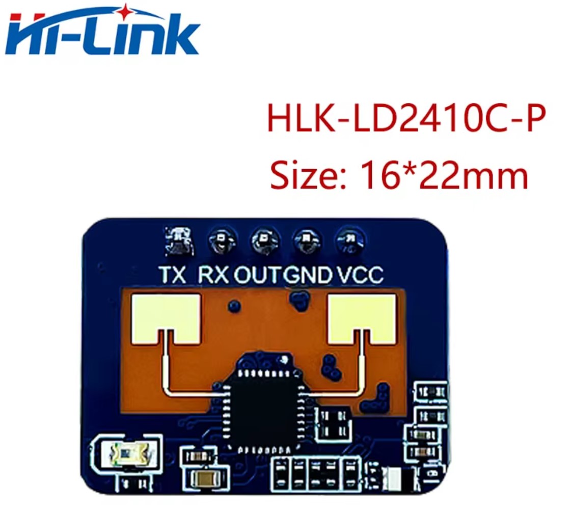
The mmWave radar sensor module used will be an HLK-LD2401C. This module has a digital output which goes high when a person is detected. The module has bluetooth capability to enable configuration from a smartphone app. A UART port also provides access to configure the device settings. Bluetooth configuration will not be used. (The app and instructions are in Chinese.) UART will be used to disable the bluetooth for security and power saving reasons. The module will be connected to a network enabled MCU to allow connection to home assistant.
Choosing an MCU
As the sensor will require network access to interface with Home Assistant an MCU with WiFi capability will be selected. For wide ranging support and ease of programming either an ESP32 or ESP8266 will be used, or alternatively a RP2040-W or analogous device could be used.
In this case I used an ESP32, specifically an ESP32-DEVKIT-V1 with an ESP32-WROOM-32 module. This was chosen for its low cost and high availability (i.e. I already had one in my draw).
Programming the ESP32
The ESP32 will be programmed using Platform IO. Platform IO is a Visual Studio Code extension that allows programming of many varieties microcontroller, along with the benefits of Visual Studio Code’s GitHub integration and large collection of extensions.
Working with the WS2812B LED Array (LED Display #2)
Part 2 of Designing a WiFi enabled LED Array Weather Display.
Choosing an MCU
As the display will require internet access to collect the weather data an MCU with WiFi capability must be selected. For wide ranging support and ease of programming either an ESP32 or ESP8266 will be used, or alternatively a RP2040-W or analogous device could be used.
Sending data to the LEDs
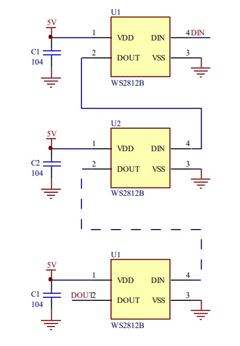
The WS2812B LEDs ar individually addressable. They use a custom single wire communication protocol and this one wire can be used to control each of the LEDs on the array. The Data In wire is connected to the Data In pin of the first LED of the array, the data out pin of this LED is connected to the Data In pin of the next LED and so on for each subsequent LED in the array.
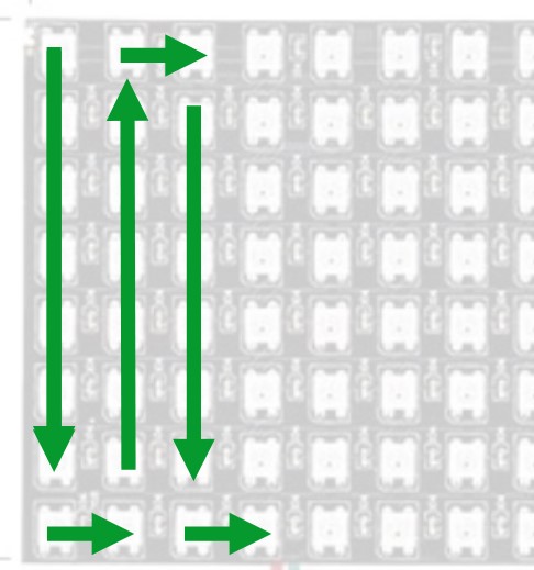
The LEDs are set up in a serpentine pattern beginning at the top left of the array and then alternately working down and back up each subsequent column like so:
Making a WiFi enabled LED Array based Weather display (LED Display #1)
This is the first post in a series documenting the development of a WiFi enabled LED array based display. The display will be used to show the current local weather forecast, provide indicators for Fire and Wind warnings, as well as likelihood of precipitation.
What is an LED Array?
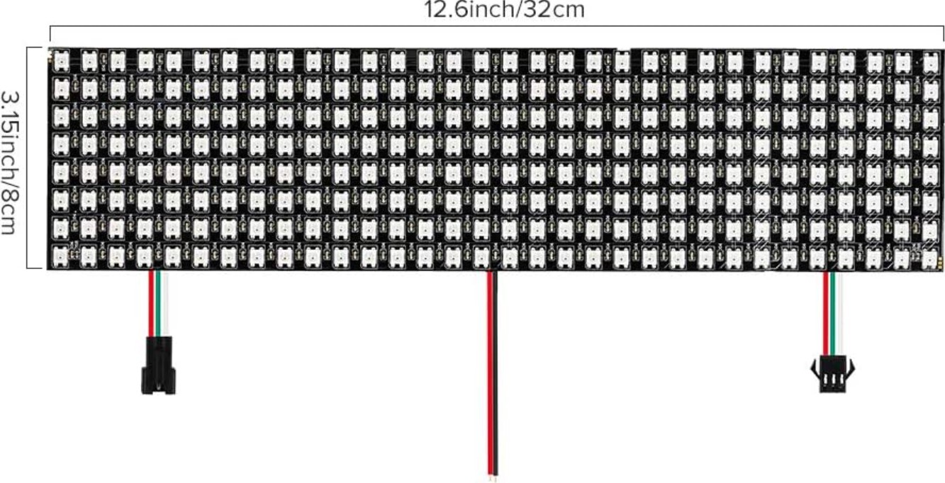
The LED array I will be using is a commonly available array of WS2812B programmable RGB LEDs on a flexible PCB substrate. The array in question is 8x32 LEDs (Amazon PN ASIN:B01DC0IPVU). Other sizes are available.
Here is the link used to purchase it: https://www.amazon.com/BTF-LIGHTING-0-24ft0-96ft-Flexible-Individually-addressable/dp/B01DC0IPVU
Why use an LED Array?
Why use an LED array rather than an LCD, OLED, smartphone, or similar display which can show far more detailed text and numbers?
While cost could be a major factor, the primary reason for using an LED array is for the ease and potential speed of information transfer. For example an LED array by the front door of your home with an indicator light for chance of rain would be an almost instant reminder to grab your umbrella. The colour and intensity of the LEDs might be a quick visual indicator that today will be hot and you don’t need your jacket. An indicator light for a High Wind alert might remind you to secure some items in your garden.
Some secondary reasons are:
- Glowing LEDs are cool.
- It’s a good excuse to learn a range of skills including embedded programming, web APIs, 3D CAD and printing etc.
- I have an LED array already…
Development process
Testing C/C++ Code Snippets, RP2040 Temp and Vsys Measurements
Test page for C/C++ code snippets.